


Network settings and traffic path
Traffic path settings are on the Network Settings page (Appliance Admin view only). The page has four tabs:
| Tab | Contents |
|---|---|
| Routing & BGP | Status strip, routed inline card, management access summary, BFD and maintenance, BGP configuration, Announcements |
| Access & TLS | Web certificate (Chapter 5), management access (Chapter 1.9), DNS servers (3.8) |
| Portal & Multi-PoP | Portal server (Chapter 2) |
| Interfaces | Interface list: role, state, speed, driver/queues |
Only admin can change these settings; other roles see them read-only.
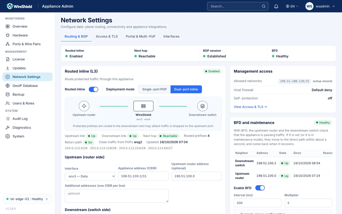
Network Settings → Routing & BGP — top status strip (Routed inline, Next hop, BGP session, BFD) and the routed inline card
3.1 Status strip
The strip at the top shows four values:
- Routed inline: enabled/disabled; a single-port POP is marked as such.
- Next hop (on a single port: ISP gateway): reachable / unreachable.
- BGP session: established, partly established or down.
- BFD: healthy, not healthy, maintenance mode or disabled.
3.2 Dual-port routed inline (L3)
Internet → Upstream router ── [upstream port] WireShield [downstream port] ── Downstream switch → servers
198.51.100.1/31 198.51.100.0/31 198.51.100.2/31 198.51.100.3/31- On Network Settings → Routing & BGP, open the Routed inline (L3) card.
- Switch on Enable routed inline mode.
- Deployment mode: Dual-port inline.
- Upstream (router side):
- Interface: the data port chosen in the wizard (XDP runs here; attacks are dropped here).
- Appliance address (CIDR): e.g.
198.51.100.0/31. IPv4 /24 to /31. - Upstream router address (optional): e.g.
198.51.100.1. Needed for the return path. - Additional addresses (one CIDR per line): optional (3.6).
- Downstream (switch side):
- Interface: the second data port (cannot be the management port).
- Appliance address (CIDR): e.g.
198.51.100.2/31. - Next hop (downstream switch): e.g.
198.51.100.3. - Advanced routing options:
- Send traffic coming from the downstream side to the upstream router: customer return traffic passes through the appliance (a separate routing table is used; the appliance's management route is not affected). Required for symmetric protection (Chapter 7.7).
- Forward traffic to destinations that are not protected prefixes to the downstream switch (unprotected): when off (default), traffic for destinations not on the Prefixes list is dropped; when on, it passes to the downstream switch without inspection. It never leaves through the management port.
- Press Save routing.
Protected prefixes (added in Chapter 9) are routed to the downstream next hop automatically; routes follow the list as it changes.
Router side (example, Junos; use your own addresses):
set routing-options static route <prefix> next-hop 198.51.100.0 preference 5
set routing-options static route <prefix> qualified-next-hop <switch-direct-address> preference 10
The second line is the backup path: if the link to the appliance goes down, traffic goes straight to the switch. Use BFD for faster failover when the appliance fails (3.4).
The card also shows the ISP/upstream and downstream link state, the number of routed prefixes, return path, unprotected traffic, clean traffic from POPs and the last error.
Disabling routed mode: Disable routed mode removes the appliance's data-port addresses and routes; traffic no longer passes through it. Change the routes on the router first.
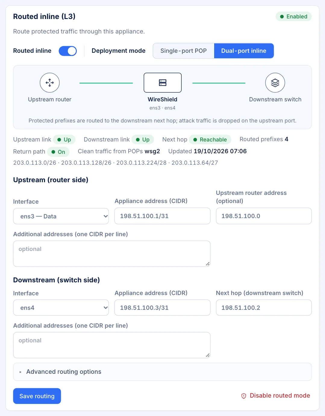
Routed inline (L3) edit form — Upstream, Downstream, Advanced routing options
3.3 Single-port POP
The ISP cable connects directly to the appliance; there is no switch or router. Traffic enters on the ISP port, is cleaned and leaves through the same port inside a POP tunnel to the POP that delivers it to customers. Anything else arriving on the port is dropped.
Prerequisites:
- In the wizard you chose the data interface as the management interface and answered
yestoUse one port for both; a separate static management address and allowed management networks are required. - A POP link (sending direction) to the delivering POP.
Steps:
- On the Routed inline (L3) card, switch it on and set Deployment mode to Single-port POP.
- ISP connection: Interface, Appliance address (CIDR) (the ISP link address, e.g.
203.0.113.2/31), ISP gateway (e.g.203.0.113.3) and optional Additional addresses. - Without a separate management network, enable Use ISP gateway as default route.
- Save routing.
A single-port POP announces the protected prefixes to the ISP over BGP, only while the POP link is healthy (Chapter 6).
3.4 BFD and maintenance mode
With BFD, the upstream router and the downstream switch check that the appliance is passing traffic. If it cannot (routed mode off, a data port down, an error in the last reconciliation) or it is in maintenance mode, the appliance stops sending BFD; the router and switch move to the direct path within about a second and come back when it recovers.
- On Network Settings → Routing & BGP, open the BFD and maintenance card.
- Switch on Enable BFD.
- Enter Interval (ms) (default 300; 50–10000) and Multiplier (default 3; 2–20).
- Save BFD settings.
- Enable BFD on the router and the switch. The card's Example Junos configuration shows ready commands with your addresses, for example:
# Upstream router — per protected prefix
set routing-options static route <prefix> qualified-next-hop 198.51.100.0 bfd-liveness-detection minimum-interval 300 multiplier 3
set routing-options static route <prefix> qualified-next-hop <direct-path-to-switch> preference 10
# Downstream switch — return path
set routing-options static route 0.0.0.0/0 qualified-next-hop 198.51.100.2 bfd-liveness-detection minimum-interval 300 multiplier 3
set routing-options static route 0.0.0.0/0 qualified-next-hop <direct-path-to-router> preference 10
Enable BFD on the appliance first, then on the router and switch; always keep the direct path as a backup next hop. Check the syntax against your Junos version.
Things to check:
- Delete the router's existing
next-hop <appliance-address>line; BFD can only be configured underqualified-next-hop. Indisplay setoutput the BFD settings appear as two lines (minimum-intervalandmultiplier); this is normal. - Loopback filter: if the router's lo0 filter ends in a
discardterm, the appliance's BFD packets are dropped. The appliance stays in Init on the panel, the router cannot bring the session up and traffic flows over the backup path, bypassing the appliance. Allow BFD from the appliance address before the finaldiscardterm:
set firewall family inet filter <lo0-filter> term allow_bfd from source-address 198.51.100.0/32
set firewall family inet filter <lo0-filter> term allow_bfd from protocol udp
set firewall family inet filter <lo0-filter> term allow_bfd from destination-port 3784
set firewall family inet filter <lo0-filter> term allow_bfd then accept
insert firewall family inet filter <lo0-filter> term allow_bfd before term <final-discard-term>- Before converting a customer prefix, test BFD with an unused /32 test route (
qualified-next-hop <appliance-address> bfd-liveness-detection …andno-readvertise); move on to the prefixes onceshow bfd sessionshows Up. Usecommit confirmedfor every change and check withshow route <prefix>that the appliance is the active path. - If the switch's return traffic does not pass through the appliance (for example its default route goes straight to the router), the switch needs no BFD; the card then shows the downstream neighbour as Down, which is expected.
For each neighbour (upstream router, downstream switch) the card shows the address, state (Up/Down/Init/Admin down), since when and the reason.
Maintenance mode (before an update or reboot):
- Press Take out of path (maintenance) and confirm. The appliance stops sending BFD; traffic moves to the direct path within about a second. Traffic is not protected until maintenance ends.
- When you are done, press End maintenance. The appliance sends BFD again and traffic returns through it.
Maintenance mode cannot be used without BFD. Disabling routed mode also ends maintenance.
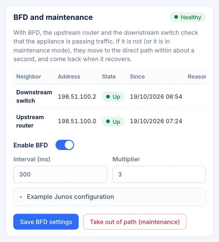
Network Settings → Routing & BGP → BFD and maintenance card — neighbour states, interval/multiplier, Take out of path button
3.5 Interfaces and port speed, FEC and rings
- Network Settings → Interfaces and the Ports & Wire Pairs page list all interfaces with their role (Data, Management, Unused), link state, speed, driver/queues, XDP mode and counters (refreshed every 5 s).
- The Ports & Wire Pairs → Link speed, FEC and rings (data ports) card shows, for each data port, the link, the current speed and the Speed, FEC, RX / TX ring and Queues (active / maximum) columns. Press Apply after a change (admin only):
- Speed (automatic or 1G–200G) and FEC: leave them on automatic unless the link does not come up. Both ends must use the same speed and FEC: 100G links usually need RS-FEC, 40G links use no FEC.
- RX / TX ring: receive/transmit descriptor ring size. Larger rings absorb bursts (fewer missed packets) at a small latency cost; empty or 0 = driver default. The field's tooltip shows the current and maximum values. At high packet rates, 4096 is recommended when the port shows missed packets (Diagnostics → System reports → Network port, Chapter 13.6).
- Changing speed, FEC or ring size briefly drops the link (a ring change asks for confirmation); do it in a maintenance window. If the new setting does not work, the previous one is restored. Settings are persistent and re-applied after a reboot.
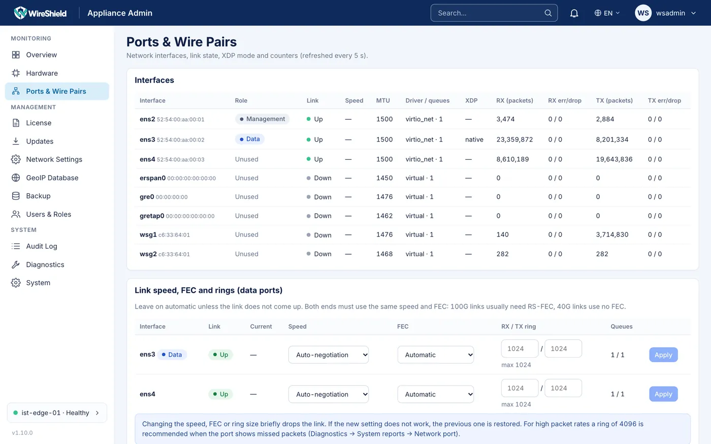
Ports & Wire Pairs — interface table and the "Link speed, FEC and rings (data ports)" card (RX / TX ring and Queues columns)
3.6 Changing addresses without interruption (additional addresses)
To change a data port's address without cutting traffic:
- On the routed inline card, enter the new address as the primary address and keep the old address under Additional addresses. Save routing.
- Move the next hop on the router or switch to the new address.
- Remove the old address from Additional addresses and save again.
Up to 4 additional addresses per port. The router/next hop can be in the network of the primary address or of any additional address.
3.7 Network diagnostics
Use Diagnostics → Network tools to run ping, traceroute, MTR and a TCP connection test (telnet) from the appliance itself. Details: Chapter 13.3.
3.8 DNS servers
The appliance resolves names for its own work: GeoIP and threat-intelligence feed downloads, Let's Encrypt certificates and e-mail. Protected traffic does not use these servers. They are first set in the setup wizard (Chapter 1.6) and can be changed in the panel:
- Open Network Settings → Access & TLS. The DNS servers card shows the servers in use.
- Press Edit (admin only).
- Enter up to 3 IPv4/IPv6 addresses, separated by commas or spaces (e.g.
192.0.2.53, 198.51.100.53). An empty field uses the default resolvers1.1.1.1and8.8.8.8. - Save. The change takes effect immediately; no restart is needed. It is written to the audit log.
If no DNS server is set, the card shows "No DNS server is set: the appliance cannot resolve names (GeoIP and feed downloads, Let's Encrypt, e-mail)." and the device status shows the health warning No DNS server is configured; saving servers here clears the warning.
The card needs the 1.10.0 operating system image or later; on older images it is not shown (install the OS update, Chapter 11.2). API: GET / PUT /v1/system/dns (Chapter 10.9).